-
Phone
86-722-3312388
-
Address
No. 348 Jiefang Road, Liushutang Industry Park, Suizhou, Hubei, China
-
E-mail


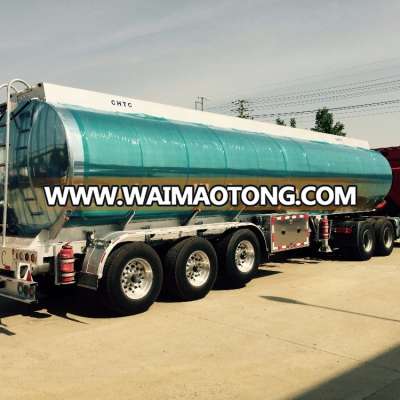
Mirror Aluminium alloy tank semi trailer 42,000L
Mirror Aluminium alloy tank semi trailer 42,000L, US $ 38,000 - 45,000 / Unit, Truck Trailer, Semi-Trailer, Aluminum / Alloy.Source from Suizhou Lishen Special Vehicle Co., Ltd. on Waimaotong.com.
Description
Aluminium alloy tank semi trailer
product features
1. 20 years manufactory experience
2. Can be customerized
3. Small order accept
4,low price,high quality and best service
tips:
1.Material:Applied carbon steel sheet Q235-A;stainless steel;aluminium alloy that in accordance with the international standard. Thickness is 5-10mm.
2.Pump system:Apply the famous pump.
3.Welding:The main parts implements automatic welding, while the accessories apply carbon dioxide welding to ensure the tank in good performance.
4.High quality in walking structure:Sub crossbeam apply rectangle steel sheet that thickness more than 5mm, stick out in one time.
5.Emergency measures: Fire extinguisher replaced on the back of the truck for the emergency.
6.Painting:Painting held more tolerance and coherence, can make sure the tank in good situation more than 10 years.
7 .According to customer’s needs:
1> The pump can be designed to pump in and out throw meter, or not through meter, self-flow through or not through meter.
2> The tank can be designed as a single compartment or several compartments.
3> You can choose to install heating pipes, insulation layer. The Insulation material is generally 50-100 mm thickness, insulation can be used rockwool, glasswool, polyurethane foam, aluminum silicate. The cladding can be used 1.8-2mm thick white (RAL9003) glass reinforced plastic, 1.2mm cold carbon steel, 1.00mm stainless steel sub-mirror or matter board.
4> At the end or side of tank, It can be installed 1-3 self-flow valve.
5> You can chosse the type of the inlet and outlet (Europ standard or normally standard).
6>Main accessories for your Option:
Flow meter / gallon meter,oil pump,Reel hose,Compartments,Aluminum ally man hole,
Stainless steel man hole,Eurostand Aluminum alloy subsea valve,Bottom loading valve.
Electrostatic reels,Anti-spill alarm system.
SPECIFICATION
A. BARREL
External Dimension |
| Approximate: 11,910 (L) x 2,500 (W) x 3,490 (H) mm Vehicles overall height shall be adjusted according to King Pin Height.
| |
Tare Weight |
|
| 6,200 kg ± 3% maximum |
Max. Payload |
|
| Case 1, loading 42,000L gasoline: 30,240 kg (fuel density 0.72 kg/liters) Case 2, loading 38,000L diesel: 33,060 kg (fuel density 0.87 kg/liters) |
Max. Gross Weight |
|
| Case 1, loading 42,000L gasoline: 36,640 kg Approx. Case 2, loading 38,000L diesel: 39,460 kg Approx. |
King pin height |
| 1220-1330mm, measure at empty load | |
Material |
| Aluminum Alloy 5454 | |
Bottom |
| 5.5-6.0 mm nominal thickness | |
Top |
| 5.5 mm nominal thickness | |
Sides | 5.5 mm nominal thickness | ||
End Head |
| 6.0-7.0 mm nominal thickness | |
Surge Baffles |
| 5.5 mm nominal thickness | |
Reference Design Code |
| UN ADR | |
Shell Finish |
| Interior – Vacuum clean Exterior – Mill finished, polished to shiny | |
Shape |
| Semi – elliptical Straight, the coaming should be approx. 25mm higher than themanholecover | |
Capacity |
| 42,000L + maximum 5% ullage | |
Compartment Number |
| Single (1) compartment | |
RolloverDamage Protection |
| With roll over damage protection along the top of the tanker, which is atleast 25mm higher than the highest place of the parts on the top of themanhole cover.Shall run the full length of the tank top and shall be integral with the tank.To prevent accumulation of liquid, drains shall be provided to direct theliquid to a safe point of discharge away from any structural component ofthe cargo tank vehicle. Drains are preferred to be through ladder rails. | |
B. FITTINGS AND PIPING
Manhole Cover & Venting |
| 2 x 20” EMCO bolted type self-latching manholecover, with P/V vent to each manhole. With mesh top alum. box to eachmanhole that not higher than the rollover damage protection system. |
Emergency (foot ) Valve |
| 2 x 4” EMCO foot valve, one at middle of bottom tanktrailer, the second at the rear of bottom tank trailer, conforming to latestedition of API RP1004 requirements. Shall be mounted internally on a sump located along the tank centerlineat thebottom of the tank. The sump depth for mounting the emergencyvalve should be 100 mm (4-inches) deep. Shall be pneumatic type, equipped with signal for OPEN / SHUT indication, and a mechanism to facilitatemanual opening of the valve in the event of accidental loss of airpressure. Shall be installed in a manner that will allow for its removal from the underside of the tank.
|
Pneumatic Control System |
| The system shall be integrated with the vehicle braking system to providebrake interlock for drive away protection during loading/unloadingoperations. With pneumatic control block for the bottom valves. |
Emergency Cut-off Switch |
| EMCO , 2 pcs |
Discharge Valve (Adapter) |
| 2 x 4” aluminum alloy API discharge valve withoperating handle, flow vision and sight glass flange locatedin the center of tanker’s right side (looking from rear trailer). |
Discharge Valve Coupling |
| Nil |
Vapor Recovery System
|
| With pneumatically operated high flow vaporvent valve, 4” vapor collection piping inside the tank connected to the 4”quick coupling type vapor adapter A drain plug shall be provided at the lowest point of the vapor adapter toallow for drainage by gravity of any accumulated product in the vaporline Vapor return piping system shall be designed to provide the lowestattainable pressure drop during operation. No rubber hoses shall beinstalled on the vapor ventpiping on the tank. Vapor Adapter shall be located to the right (curb) side of the tank truck,in an area adjacent to and left of the bottom loading adapter(s). Thehorizontal distance between the vertical centerline of the Vapor Adapterand left most Bottom-LoadingAdapter shall be 350 mm. The verticaldistance (height) between the horizontal centerlines of the VaporAdapter and the Bottom Loading Adapter(s) shall not exceed 200mm.
|
Barrel Bottom Piping |
| 4” aluminum alloy piping system for each compartment, designed to keepthe overall pressure drop as low as practicable under design flow condition. Design working pressure for piping shall be 5 bar . Piping shall betested for a test pressure of 1.5 times the working pressure. Piping originating from the emergency valve(s) and leading to the bottomloading adapter(s) shall have a downward slope with respect to horizontallongitudinal axis of the cargo tank to facilitate product flow. |
Anti–Static System |
| With 3 meters length retractable wire reel for anti-static, located atdischarge valve control area |
Overfill Protection System |
| The design of the overfill prevention system shall conform to the requirements stipulated in the latest edition of API RP1004 With EMCO 5 wires optic overfill protection system, consisting of thefollowing: A five -(5) wire system optic sensing probe in each compartment, mounted either directly in the accessory port of the manhole coverassembly or alternatively into a 50mm (2 in.) NPT fitting secured to thetank shell.Designed for a temperature range of -20°C (-4°F) to+60°C (+140 °F) and shall have fog resistantcharacteristics. The response time from sensor going wet to the change ofstate of the signal at the interface six-pin receptacle shall not exceed 0.5seconds. |
Level Reading Stick |
| Nil |
Antistatic Internal Cable |
| An Antistatic Internal Cable Conductor between top and bottom of tankshell shall be provided.The cable shall be made of stainless steel materialand installed between the Emergency Valve sump and the underside of theManhole Cover (in the vicinity of the overfill sensing probe) close to thecenter of tank shell. |


we are not only manufacturer and we are also the best service and sales